Project Overview
The existing hydropower facility on Pine Creek produces 2.1 MW. The proposed Atlin Hydro Expansion Project (AHEP) would increase this energy production by 8.5 MW, for a total of 10.6 MW.
In order to generate this energy, the Atlin Hydro Expansion Project would use the infrastructure of the existing hydro facility (eg. reservoir, weir, tailrace) and build new infrastructure, as well.
New infrastructure includes:
- 2 powerhouses
- 2 power canals
- 2 penstocks
- 2 weirs
- 2 substations
- powerlines
Put simply, water would be collected and held back in the Surprise Lake reservoir over the summer months, then released in the winter months to generate power. This energy would then be exported to the Yukon via a proposed 92 km transmission line along the Atlin Road. The Project would operate primarily in winter, from October to May.
But what does this new infrastructure look like? How does it work? Where will it be? The following sections help provide answers to these questions, beginning with how hydropower works in general, how the existing hydropower facility works, and finally the function and design of the proposed facility.
For more detailed information on the proposed infrastructure, we invite you to download the AHEP Information Guide.
How does hydropower work?
Hydropower facilities include many components that are designed to harness the energy of moving water. Because the flow of rivers and creeks changes depending on the climate and the time of year, many hydropower designs involve regulating the release of this water. This way, energy can be captured throughout much of the year, rather than only during one season.
To accomplish this for our Project, we need a place to store the water (a reservoir), a structure to control the water’s release, and a channel or pipe along which to move the water to a turbine (located in the powerhouse). In the powerhouse, the force of moving water turns the turbine, which generates electricity. Finally, we need a powerline to transport this electricity to a substation, where it can be made available to consumers via powerlines.
What's involved in the existing operation?

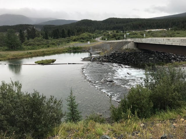
Currently, Xeitl Limited Partnership (XLP) uses Surprise Lake as the reservoir for the existing 2.1 MW hydropower facility. The structure to manage the water’s release is a rockfill weir (located at the bridge at Surprise Lake). The weir is basically a barrier that helps to hold back the water at Surprise Lake. While water spills over the weir at some times of the year, a gated pipe below the surface further controls the water’s release. The water then flows down Pine Creek where a concrete dam holds the water back in a headpond. From this headpond, the water flows into a penstock, a pipe that also has a mechanism for controlling the water’s release.
This headpond is called a “penstock intake headpond,” because it is a headpond from which the penstock “takes in” water. The penstock then carries the water ~4 km down to the existing powerhouse where the moving water forces the turbine to turn, generating electricity. Finally, the water flows out of the powerhouse along a channel called a tailrace, back into Pine Creek. Energy generated at this powerhouse is transferred to the BC Hydro substation.

The existing hydropower facility affects water levels at Surprise Lake and flows in Pine Creek. A detailed discussion of water levels can be found in the AHEP Information Guide in the sections titled “What Happens at Surprise Lake” and “What Happens at Pine Creek.”
What's involved in the proposed operation?
To generate more energy from Pine Creek, which will offset winter burning of fossil fuels, more water must be available to feed two new powerhouses. This requires “holding back” more water at the reservoir at Surprise Lake and diverting (via canals and penstocks) more water from Pine Creek.
The following provides an overview of the new infrastructure (powerhouses, weirs, etc.) required to generate and export this energy to consumers. This overview will follow the same path the energy takes – from its start as water held back at Surprise Lake, through to the turbines and along powerlines to the Yukon.
Increased water storage on Surprise Lake
“Storage range” refers to the difference in water level at the reservoir, but more specifically the required range of water level for the hydropower facility to operate. “Full supply level” and “low supply level” are the terms used to refer to these operational levels. (These terms are sometimes confused with “average high water” and “average low water.” For a discussion of these terms, visit our FAQ page.)
For the proposed Project, the storage range would increase from approximately 1.1 m to 2.0 m. By increasing our ability to store the water that currently spills over the existing weir, more energy can be captured for power production throughout the year.
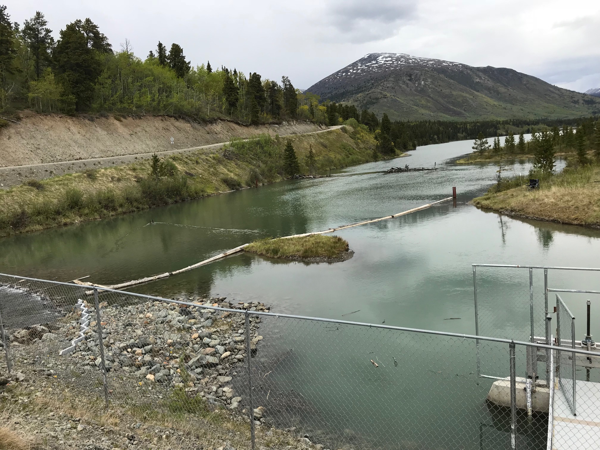
To increase this storage range, we need the reservoir – Surprise Lake — to hold more water. To this end, we would raise the height of the existing rockfill weir by 0.7 m. (These levels are discussed in detail in the section titled “What Happens at Surprise Lake”). This would be the new full supply level. The low supply level (the lowest level the lake can be drawn down while still allowing water to flow through the gated pipe) would be lowered by 0.2 m. This lowering would be accomplished by removing some sediment from upstream and downstream of the weir.
This structure – the rockfill weir and gated pipe – is called the Surprise Lake Control Structure.
(There are no proposed changes to the existing concrete dam downstream of the Surprise Lake Control Structure.)
Construction of an upper powerhouse adjacent to existing facility (expansion)
An upper powerhouse would be constructed with two Francis turbines. This powerhouse would be located beside or attached to the existing XLP powerhouse building. The two powerhouses would share the tailrace, which would be expanded to accommodate this additional facility. This upper powerhouse would be capable of producing ~5.7 MW of power.
Water for the upper powerhouse would be diverted from Pine Creek (with the flow at ~4.7 m3/s) into the upper power canal. The location of the start of this power canal would be about 2.5 km downstream of Surprise Lake, at the same location as used in 1908 for an existing, historical mining ditch. To divert the water from the creek to this canal, a new rockfill weir would be constructed.
This weir would create a headpond for the power canal. The amount of water entering the upper power canal from this headpond would be controlled by a gated pipe under Surprise Lake Road. This proposed structure – the new rockfill weir, headpond and gated pipe – is called the Upper Pine Creek Control Structure.
The upper power canal would be approximately 8 km long, making use of an existing 6 km-long mining ditch, or flume, developed in the early 1900s, which terminates near the historic Dredge and Flume Site. The remaining ~2.0 km section of the power canal would be developed, avoiding the historic Dredge site.
The canal would terminate at a penstock intake headpond, located at an elevation of about 176.5 m above the upper powerhouse.
From this headpond, water would be conveyed into the penstock. The first ~750 m of the penstock would drop ~70 m in elevation before running parallel to the existing penstock for the remaining ~4 km. In other words, the new penstock would be constructed within the footprint and clearing of the existing penstock right-of-way.
After cycling through the turbines to generate energy, the water would be released into the tailrace of both the upper powerhouse and existing powerhouse and returned to Pine Creek. The existing tailrace would be expanded to accommodate the additional volume of water.
Construction of a lower powerhouse below Warm Bay Road
A lower powerhouse would be constructed with a Francis turbine. This powerhouse would be located ~4 km downstream of the existing and proposed upper powerhouse.
Downstream of the upper powerhouse expanded tailrace, Spruce Creek merges with Pine Creek. Here, the water would be re-captured by another new rockfill weir, headpond and gated pipe on Pine Creek. This proposed structure is called the Lower Pine Creek Control Structure. This means that the water used for energy production in the upper powerhouse would be reused to generate energy in the lower powerhouse.
This rockfill weir would create a headpond on Pine Creek, from where water would be conveyed into a lower power canal. In addition to water from Pine Creek, the lower ~100 m of Spruce Creek would also be diverted into this headpond, so that all the water from Spruce Creek would enter this lower power canal. This ~600 m-long power canal would be located on the south side of Pine Creek. Combined, approximately 6 m3/s of flow from Pine Creek and Spruce Creek would be diverted into this lower power canal, ending at a penstock intake headpond.
This penstock would run approximately 3.2 km to the lower powerhouse and would be located near Pine Creek. It would cross the Warm Bay Road at the Pine Creek Campground and travel ~600 m south, before entering the lower powerhouse.
The tailrace would move the water into Atlin Lake directly. This tailrace would act like an extension of the lake, with water rising and falling with natural lake levels, and the flow being slow. The tailrace would be approximately 500 m long, and ~17 m wide at high water, and would include fish habitat in its design at the outflow into Atlin Lake.
Construction of a 25 kV powerline
A powerline would convey the energy generated from the lower powerhouse to a new substation. This substation would be located next to the upper powerhouse. As proposed, the powerline to this substation would generally follow the route of the penstock, except along a portion of Warm Bay Road, where it would be on the opposite side of the road to avoid BC Hydro distribution lines.
Construction of a 69 kV transmission line to export power to Yukon
Power would be exported to Yukon’s grid via a 92 km 69 kV powerline. This line would originate from a new substation, constructed at the upper powerhouse, and travel northwest to Como Lake. From there, the powerline would travel along Atlin Road to Jakes Corner, where a second new substation would be located. Although the powerline would generally be located within the Atlin Road right-of-way, additional clearing would be required. This involves an average width of 7.5 m of additional clearing in BC, and an average width of 5 m in Yukon.
The design of the powerline generally includes 55 ft high western red cedar poles, with 3-strands of wire, but individual pole heights may vary (higher or shorter) to accommodate the terrain.